


Lupine Publishers Group
Lupine Publishers
ISSN: 2643-6736
Research Article(ISSN: 2643-6736) 
Technical Evaluation of the Glues Pumping System in the Cuban Nickel Industry Volume 4 - Issue 2
Received:September 13, 2023 Published: October 09, 2023
Corresponding author:Deynier Montero Góngora, Higher Mining Metallurgical Institute of Moa, Caribbean
DOI: 10.32474/ARME.2023.04.000184
Abstract
The Commander Pedro Sotto Alba Company - Moa Nickel. S. A constitutes an important source of income for Cuba in the production and export of mixed nickel and cobalt sulfide. Within the technological process, the pumping system of the Countercurrent Washing plant plays a transcendental role in the transportation of waste for final disposal. The glue pumping system has presented difficulty in transferring the waste to the furthest point from the North Extension, with frequent overflows of the glue tank being observed, as well as breakdowns in the technological line. As a solution, a technical evaluation of the tail pumping system was carried out using a mechanical energy balance. The results of the evaluation made it possible to determine the insufficient tail pumping capacity with flow values below the design (3 900 gpm), pressures in the system of (213 psi) above the design limit pressure (185 psi) to protect the pipeline, as well as restrictions in the system given by the different heights (14, 17 and 20 m) that the dam will have as the tail is stored and significant changes in the diameter of the line from 18 to 16”.
Keywords: mixed nickel; cobalt sulfide; tail pumping system; mechanical energy balance
Introduction
To the north of the province of Holguín, specifically in the municipality of Moa, are the largest reserves of lateritic ores in Cuba. Lateritic ores are made up of complex compounds of great commercial interest, as they constitute the fundamental raw material for the production and export of mixed nickel and cobalt sulfide. Acid leaching at high temperature and pressure is the technology used by the company Moa Nickel SA “Pedro Sotto Alba” for the processing of lateritic ores. This technology presents high standards in nickel and cobalt (Ni and Co) extraction efficiency, with values in the range of 85 to 88%. A total of 12 plants are involved in this process to obtain mixed Ni and Co sulphide, seven so-called main hydrometallurgical plants and five auxiliary ones. In reference to the technological flow, the hydrometallurgical plants are: Pulp Preparation, Pulp Thickeners, Leaching, Laundries, Neutralization, Sulfide Precipitation and Sulfide Drying. The Ni and Co contents present in the crystalline structure of the lateritic ores are extracted through a selective solvent, becoming concentrates dissolved in the leached pulp. This pulp is processed at the Lavaderos plant with the objective of obtaining a clarified liquor, concentrated in Ni and Co. In this section of the process, 10 sedimentation tanks operated in series are involved. These pieces of equipment are called washing stages, with three high-capacity and seven conventional ones according to their design.
The main function of these tanks is to clarify, washing the pulp extracted from the previous stage in countercurrent with the liquor from the subsequent stage. The dosage of flocculants and other chemical compounds is one of the technological variants used in these settlers. This alternative allows to accelerate the sedimentation process of the solids and favors the decantation of the liquor concentrated in Ni and Co. At the Laundry plant, a residual flow greater than 3,500 gpm (> 794 m3/h) is generated, called waste tailing, which is pumped to the storage dam. A tank (153-TK-10) intervenes in the management of this waste, where, under optimal process conditions, it receives the bottom pulp from the last stage. This tank treats other waste effluents from collection wells located in the process plants, an action that dilutes the output tail. The transfer of waste from the Laundry plant is carried out through a hydraulic station, made up of three high-speed centrifugal pumps and a network of pipes resistant to wear and tear due to friction of erosive particles. The current pumping circuit for the waste generated at the Lavaderos plant has been intervened on two occasions to make technological improvements. In 1998, the carbon steel lines lined internally in rubber were replaced with High-Density Polyethylene (HDPE), maintaining the design diameter of 18 ". This modification was made taking into account the mechanical wear of the lines of this system, due to the end of its useful life; a fact that caused limitations in the factory's production and environmental incidents due to frequent waste spills. The second improvement was carried out in 2011, where the first 1.35 km of pipeline was replaced. 18 " by a 24 " HDPE, parallel to the existing one. The project was executed to increase the efficiency and stability of pumping the waste to the dam.
In [1] a study of the hydraulic transport parameters of the lateritic pulp pumping facility of the Moa Nickel SA company was carried out and a rheological analysis was carried out, obtaining a real plastic behavior, whose flow curve is described by the rheological model. by Herschel - Bulkley. In [2] work was done on the design of a pumping system with the aim of increasing productive efficiency in glue transportation, to reduce breakdowns and installation costs. In [3] the entire hydraulic network was analyzed through a mechanical energy balance and the load needs from the Laundry plant to the North Extension were determined, also including the different projected reinforcement points (Water Plant “A” and Station 102+00 in Veguita). The depletion of the dam's storage capacity has conditioned the need to create new capacities to the north, “Northern Extension” and to the southeast of it, “Area 22”. The new location, called Northern Extension, has increased the transportation distance to 3.7 km. The new section of line required for transfer to the North Extension is installed with a restriction in the diameter of the pipe, decreasing from 18 to 16 ". Under the current conditions of the system, effects on pumping efficiency have been observed, such as frequent overflows of the 153-TK-10 tank and an increase in system pressure. It is known that, with the current changes in the scheme, it is necessary to carry out a mechanical energy balance and identify a new system design that guarantees pumping efficiency.
Materials and methods
To measure the different variables present in the hydraulic system, the following measuring instruments were used (Table 1).
Table 1: Characteristics of the measuring instruments.

Methodology for hydraulic calculation of the tailings pumping system
The following calculation methodology provides the necessary expressions to obtain the curve that characterizes the behavior of the non-Newtonian fluid along the line; The loading height of the network is also taken into account depending on the flow.
Fluid velocity
To determine the speed of the tail inside the line or pipe, the continuity equation is first taken into account, which expresses the following:
Where:
Q: Fluid flow rate; m3/s
: Fluid velocity (tail); m/s
A: cross-sectional area of the pipe; m2
By solving for the velocity and substituting the expression to find the area in a circular section, we obtain:
Where:
D: Pipe diameter; m
Determination of the friction factor in simple pseudoplastic fluids
The rheological equation for simple pseudoplastic fluids with y n < 1, according to Waele's Ostwald rheological model is:
Where:
τ : Shear stress; Da
K: Mass consistency index of the fluid
γ: Velocity gradient; s-1
n: Flow rate
The calculation method can be described as follows:
1. Calculate the generalized Reynolds number, which is defined with the following expression:
Where:
Re: Generalized Reynolds
v : Fluid velocity; m/s
pp : Density of tails pupa; kg/m3
For Re < 2100, a laminar regime is determined.
For 2100 < Re < 4000, there is a transition period, that is, it is the transition from the laminar regime to the turbulent regime.
In this regime, including the transition regime, the Fanning friction factor (f F) is calculated:

For Re > 4000, a turbulent regime exists.
For turbulent regime, the Fanning friction factor was obtained graphically (figure 1).
2. With the generalized Reynolds and n, the Fanning friction factor (fF) is obtained with the graph obtained by Dodge and Metzner adapted by Levenspiel, which is presented in figure 1, keeping in mind that f F = f /4, where f the friction factor of the Darcy equation.
3.Calculate the losses with the Darcy formula and the dynamic head of the pump.
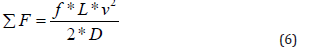
Figure 1: Dodge and Metzner graph for pseudoplastic or dilatant materials. Source: [4].

Sum of friction forces in the pipe (J/kg)
f: Friction or fanning factor (dimensionalless)
L: Pipe length (m)
D: Inner diameter of the duct (m)
Mechanical resistance of the line
In [5] the Darcy formula is indicated to calculate the mechanical resistance offered by the pipe through which the fluid is transported:
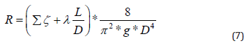
Where:
R : Mechanical resistance coefficient of the line; s2/m5
ξ: Local loss coefficient of the line
λ : Darcy friction factor, in this case =
L : Line length; m
g : Gravity constant; m/s2
In the plant's tailings pumping system there are two evacuation lines of different diameters. From the station exit, the line has a branch that gives rise to the existence of two lines. One 18" (45.72 cm) in diameter, and another 24" (60.96 cm) in diameter; For the evacuation of the tail pumping system, only the 24" diameter line was used, which is the line that is currently in operation, since the 18" line has presented pumping restriction problems due to the remoteness of the cells. to Northern Extension. The topographic information reveals that the 24" line has a section of 1,350 m, in total length, then it is reduced to a diameter of 18" with a length of 520 m and subsequently reduced to a diameter of 16" (40.64 cm) with a length of 4 800 m. The suction and discharge height of the pumps was also taken into account, measured from their horizontal level, taking sea level as a reference. The optimal level of operation of the tailings tank for hydraulic calculations was 50%, since in the operations of the system it could be observed that, at lower values of these, it causes cavitation in the pumps and at values above it causes sanding in the tank. Using equation 8, coming from the solution of D. Bernoulli's equation for the real liquid flow, it is possible to obtain the loading height of the network.
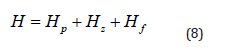
Where:
H : Network discharge height; m
Hz : Head load between pump suction and discharge; m
Hp : Pressure head between pump suction and discharge"; Pa
Hf : Friction load for line "; m
Characteristic parameters of turbomachines
For hydraulic calculations of a system, it is important to take into account the parameters that evaluate the operation of the pump. By obtaining the characteristic or operating curve of the pump it is possible to find the hydraulic power (N), the performance (Ƞ), and the cavitation regime in said turbomachine.
Hydraulic power
To calculate the power, it is necessary to define the operating curves of the system pumps for different flow values (Q). In this case, the Chinese-made supplier's characteristic curve catalog [4-6] was used for the 356-PU-1A/B pumps and the catalog [7] for the 356-PU-1C pump. (Figure 2, 3) show the characteristic curves of each pump installed in the system. It is important to highlight that the 356-PU-1A pump is the same as the 356-PU-1B since they have the same characteristics and dimensions; these Chinese-made pumps that were purchased were installed in these positions. Taking into account that the mentioned pumps have a speed variator in the motor, the hydraulic similarity criterion was used to find the new conditions of the operating curves for the system pumps (Table 2).
Figure 2: Characteristic curve of the 356-PU-A/B pumps taken from the catalog by the supplier [6].

Figure 3: Characteristic curve of the 356-PU-1C pump taken from the supplier’s catalog [7].

Table 2: Load heights of the system pumps for different flow values.

Similarity criterion
If it is considered that the work regimes are similar for the same pump,
with different numbers of revolutions and, then the similarity formulas are simplified and become the following [5]:
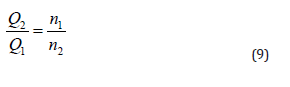
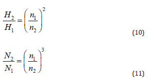
Subscript 1 indicates the parameters of the original pump. Likewise, subscript 2 refers to the new parameters that arise when the rotation speed varies.
Discharge pressure
It is known that in the system two pumps are kept operating continuously and one in an unloaded branch, so a study is made of the working pressure that intervenes in the discharge of each pump. It can be known through the following formula:
Where:
P: Pump discharge pressure; Da
g: Gravity constant; m/s2
H: Pump head height; m.c.H2O
Results
Table 3 shows the different values obtained in the hydraulic calculation of the current system, referring to the load heights and pressures required for the 153-PU-1C booster pump at North Extension. The levels of the dam are taken into account in the different phases of the project for the deposition of tailings at the furthest point from the dam. For the different heights of the dam in North Extension and with the current diameters of the lines in the hydraulic network, table 3 shows the values of each load and pressure required, as well as the flow rates reached by the 153-PU-1C pump. in the current and future conditions of the project. It can be observed, regarding the required load and pressure, that in both cases there is no significant variation in these parameters. However, in the pumped flow there is a tendency to decrease as the height of the dam increases at the furthest point from the dam: from level 14 to 17 there is a decrease in the flow of 56 gpm, from level 17 to 20 decreases by 57 gpm and from level 14 to 20 a difference of 113 gpm. In the three cases in which the height of the dam increases as the tailing is stored, the flow values cannot reach the original design value of the pump 3,900 gpm, however, if the average pumped flow is exceeded 3,600 gpm in the evaluated period, this indicates that there is difficulty in pumping when the waste is sent to the furthest point in North Extension. When analyzing the current system for the different heights of the dam in North Extension, it is inferred that there is a restriction in the system, this is given not only by the changes in the height that the dam will reach as the tailing is stored, but also due to the significant changes in diameter that the line has along the hydraulic network.
Table 3: Load requirements depositing the tail to the North Extension.

Proposal for a variant of technological improvements in the queue transportation scheme of the Laundry plant
To guarantee stable pumping to the dam, a detailed study is necessary to determine the load requirements from the plant to the most critical point projected in the North Extension, and to define from the analysis if it is necessary to locate reinforcement points for pumping, based on the process design criteria and complying with the flow and pressure parameters for current and future operation.
Pumping load requirements
In this case, 4,200 gpm was taken as the design flow based on studies carried out by [3] on the queuing system. Table 4 shows the load and pressure values required in the system for a design flow of 4,200 gpm and those obtained at the reinforcement points at North Extension. As can be seen in Table 4, with the current piping system for a design flow of 4,200 gpm, 184 m of head are needed in the plant, equivalent to 382 psi. Therefore, in the plant as in any of the projected reinforcement points, the required pressure exceeds the design pressure of the pipe (200 psi) by a wide range. The restriction is the 16" pipeline in the Cola Dam area, with a length of 4,800 m. Taking into account that the required pressure (382 psi) is higher than the design pressure of the HDPE pipe (200 psi) and that the other reinforcement points show the same behavior, caused by the decreases in the diameters of the pipe. the hydraulic network, especially the 16"; it is proposed to resize the piping system in order to achieve a pressure no greater than 185 psi, which is the design pressure to protect the HDPE pipe. For this it is necessary to replace the 18" pipes. and 16 ", for another with a larger diameter. Table 5 shows the load and pressure values required at the reinforcement point in the stream (Est. 102+00”) to the furthest point from the North Extension. (cell 3), taking into account that this station is closer to the waste deposition site and the projects related to the storage of tailings, such as in Area 22 (southern extension of the old dam) projected in 2022 and in the Los Lirios area as one of the tentative variants currently being analyzed by the company. Table 5: Load and pressure requirements in (Est. 102+00”) for different line diameters.
Table 4: Load requirements for the new reinforcement points.

Table 5: Load and pressure requirements in (Est. 102+00”) for different line diameters.

From the results obtained, it can be observed that there is an increase in these analyzed variables (load and required pressure) at the proposed reinforcement station (Station 102+00), as the diameter of the pipe is decreased along the network. hydraulics.
Resizing the line system
When considering the behavior of the calculated values, it is proposed to resize the line system in order to achieve a pressure no higher than the design pressure (185 psi), to protect the HDPE pipe. It is also important to consider the speed recommended by designers for these types of pipes (1-2 m/s). Table 6 illustrates the velocity values for the different pipe diameters, for a design flow of 4,200 gpm. As can be seen, the 24 and 22 "pipes meet this requirement. In the case of the 20" line, it could be used if the design engineers consider its reliability for the characteristics of the fluid.To resize the pipes, the calculations showed that the 18 and 16 " lines are the ones that offer the greatest restriction to flow, especially the 16 ", as it is the smallest diameter and longest (4,800 m), therefore, It is advisable to replace it with pipes with diameters of 24 or 22 ".
Table 6: Glue speed for different diameters of HDPE pipes (DR9).

Final arrangements of the hydraulic diagram
By estimating that the significant change in the diameter of the hydraulic network lines is a fundamental cause of the existing restrictions in the tailings pumping system and that it brings limitations in the stability of the pumping and sometimes overflowing of the tailings tank; Table 7 establishes the final arrangement of the pipes that would provide greater security in the transfer of waste to the most critical point of waste deposition.According to the results of table 7, the current length (5 320 m) of 18 and 16 "pipe should be replaced by 22". Under these conditions, it is recommended to purchase two new centrifugal pumps for this service, each with a capacity of 4,200 gpm and 39 m head.
Table 7: Final arrangement of tailing pipes to North Extension for 4,200 gpm.

Conclusion
1. The evaluation carried out on the tail pumping system through the mechanical energy balance demonstrated:
a. The pumped tail flow values for the different heights of the dam (14, 17 and 20 m) at the furthest point from the North Extension do not reach the design value of the pump (3,900 gpm), which indicates that there is difficulty in the transfer of waste.
b. The pressure values required in the system (213.53 psi) calculated for the aforementioned heights exceed the system design pressure of 185 psi, a limit taken to protect the HDPE pipe.
c. It is deduced that there is a restriction in the given system due to the height of the dam and the significant changes in the diameter of (18 to 16”) in the line along the hydraulic network.
2. The results obtained in the calculations carried out for the variant of technological improvements in the new design allowed:
a. Use a pumping system located at Station 102+00 Veguita, guaranteeing the transfer of waste at 4,200 gpm, higher than the design value of
b. 3 900 gpm pump installed.
c. Achieve pressures in the system of (80.29; 90.12; 112.15 psi) at different heights of the dam, below the limit pressure (185 psi), to protect the pipeline.
d. Resize the existing 16 and 18 " technological lines to one with a larger diameter, because these offer flow restrictions, especially the 16 " one as it is the smallest diameter and longest (4,800 m).
References
- World Health Organization.
- Los Angeles magazine.
- Pomerleau DA (1988) ALVINN: An Autonomous land vehicle in a neural network.
- LeCun Y, Muller U, Ben J, Cosatto E, Flepp B (2005) Off-Road Obstacle Avoidance through End-to-End Learning.
- Bojarski M, Testa DD, Dworakowski D, Firner B, Flepp B, et al. (2016) End to End Learning for Self-Driving Cars.
- Siegel JE, Pappas G, Sun Y (2009) A gamified simulator and physical platform for self-driving algorithm training and validation.
- (2020) Robotic Operating System.
- Zhang Q, Du T, Ch Tia (2019) Self-driving car trained by Deep reinforcement learning.
- (2020) Blender.
- (2020) Unity.
- (2020) Amazon.
- (2020) Adafruit.
- (2020) SainSmart Wide Angle Fish-Eye Camera Lenses.
- (2020) NVIDIA DRIVE PX Pegasus.
- (2020) Arduino.
- (2020) Raspberry Pi 3b+.
- (2020) Orange Pi.
- Fukushima k (1980) Neocognitron: A Self-Organizing Neural Network Model for a Mechanism of Pattern Recognition Unaffected by Shift in Position. In Biological Cybernetics 36(1980): 193-202.
- Lecun Y, Bottou L, Bengio Y, Haffner P (1998) Gradient-based learning applied to document recognition. In 88(11): 2278-2324.


-

Mark E Smith
Bio chemistry
University of Texas Medical Branch, USA -

Lawrence A Presley
Department of Criminal Justice
Liberty University, USA -

Thomas W Miller
Department of Psychiatry
University of Kentucky, USA -

Gjumrakch Aliev
Department of Medicine
Gally International Biomedical Research & Consulting LLC, USA -

Christopher Bryant
Department of Urbanisation and Agricultural
Montreal university, USA -

Robert William Frare
Oral & Maxillofacial Pathology
New York University, USA -

Rudolph Modesto Navari
Gastroenterology and Hepatology
University of Alabama, UK -

Andrew Hague
Department of Medicine
Universities of Bradford, UK -

George Gregory Buttigieg
Maltese College of Obstetrics and Gynaecology, Europe -

Chen-Hsiung Yeh
Oncology
Circulogene Theranostics, England -
.png)
Emilio Bucio-Carrillo
Radiation Chemistry
National University of Mexico, USA -
.jpg)
Casey J Grenier
Analytical Chemistry
Wentworth Institute of Technology, USA -

Hany Atalah
Minimally Invasive Surgery
Mercer University school of Medicine, USA -

Abu-Hussein Muhamad
Pediatric Dentistry
University of Athens , Greece
